The hand cranked MP3 player
This is a writeup of a recently finished art project that me (tms) and MMN-o were involved with.
Background
Some time last year Tryggve Lundberg (assistant professor at Umeå Academy of Fine Arts) approached us for assistance with an art project (Klangvägen). The gist of it was to be able to play random MP3 files from a memory card by cranking a handle, and that this device would be sitting in a box on the side of a cast iron pole in the middle of the woods. This meant no nearby outlets, and that there would have to be some kind of generator inside the box and some way to temporarily store electricity. There would also be two installations, meaning two sets of electronics.
Playing MP3s proved to be the easiest part, as that could be done by an Arduino with an MP3 shield. We ended up going with a Music Shield V2.0, which worked without problems. The real problem was providing power. We tried a few different approaches to this problem, presented below.
Less successful attempts
Some back-of-the-envelope calculations showed that a capacitor bank could do the job, but getting suitable double-layer capacitors (aka supercapacitors) delivered at a reasonable price would take a while. Until then we needed a stop gap solution in the form of a LiPo battery charged by a solar cell. This worked somewhat OK until winter, when the low amount of sunlight meant the battery would run out and need to be charged regularly. Far from ideal, and it proved some kind of generator was required.
Initially we had thought that a stepper motor could be used as a generator since they deliver quite high voltages when turned. Unfortunately they need to be turned quite quickly to generate this voltage, meaning a gearbox would be needed. More problematic was that stepper motors aren't particularly good at generating usable amounts of current. In the end the steppers could only be used for detecting that the crank was moving (an important feature), with power supplied from the LiPo.
With the LiPo solution in place the order of ten supercapacitors eventually arrived: 500 Farad, with a maximum voltage of 2.7 Volts. We reasoned two or three of these in series would offer plenty of capacity for the project, and would handle 5 V quite well. What we didn't consider is that 500 F takes quite a bit of current to charge at any reasonable rate - hooking one up to a bench supply with current set to 3 A it takes about five minutes to reach full charge (dV/dt = I/C). Clearly the capacitance was too large, which we hadn't conceived as something that could ever be a problem. Back to the drawing board.
To remedy the capacitor situation we drank some coffee, took measurements and made further calculations. The Arduino + Music Shield + speaker would draw 70 mA regardless of input voltage, and work down to 3.8 V. One minute of runtime at 5 V works out to 21 Joules of energy. At this point we still reasoned that stepper motors could be used as generators, and that high voltage tolerance was most important. In other words, string a bunch more capacitors together for higher voltage and lower capacitance. So we ordered a batch of 25 Farad caps this time around, which proved much more reasonable. Unfortunately it again became clear the the capacitance was too high, and bringing it down further by stringing more capacitors in series ended up taking too much space.
[caption id="attachment_941" align="alignnone" width="300"] Twelve 25 F supercaps in series on a 160x100 perfboard. Twenty-four of them (covering the entire board) would bring the capacitance down to almost-OK levels, but still way too bulky. The only upside was high max voltage (64 V).[/caption]
In the end we realized "smaller is better" and that we could better customize max voltage and capacitance of the energy bank by ordering lots and lots of 1 F caps. One hundred of them to be precise, luckily cheaper than you'd think. The only potential downside would be more soldering (it ended up being less).
The solution
After throwing out the idea of using stepper motors for generators we realized the simplest, most obvious replacement: bicycle hub dynamos. These things are made to turn at low RPMs, removing the need for a gearbox. They also put out roughly 3 W of power which is quite respectable and, more importantly, enough to reach 21 J in seven seconds.
[caption id="attachment_942" align="alignnone" width="244"]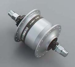 Hub dynamo[/caption]
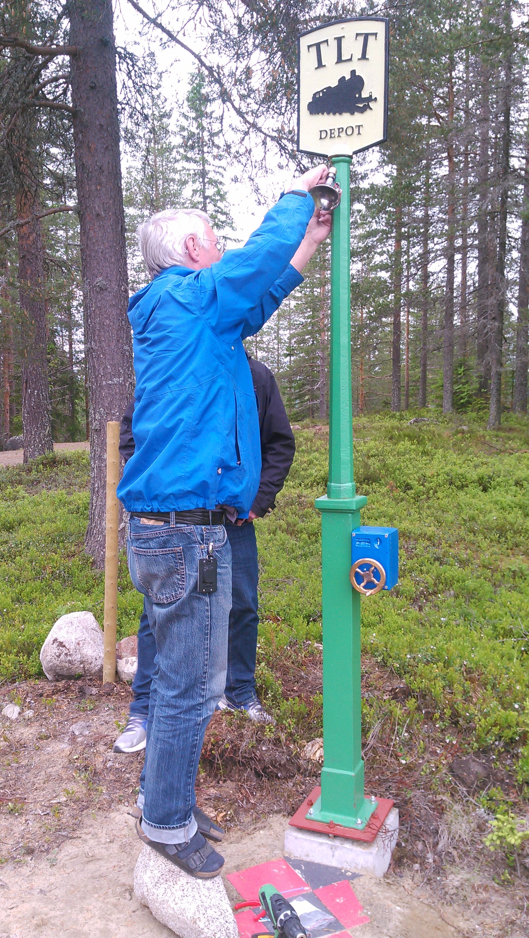
Playing around with the dynamos we found the following: they put out AC, and the open-circuit voltage is around 30 VAC. Another complication is that the shaft stays stationary while the hub spins. Tryggve was able to build a kind of adaptor that fixed this problem, and the shaft could be screwed into the box and secured with a washer and nut. A bronze crank completed the generator assembly.
Circuit
[caption id="attachment_954" align="alignnone" width="300"]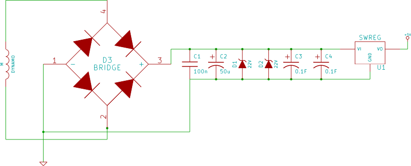 Schematic of the power part of the circuit[/caption]
Turning the 30 VAC from the dynamo into 5 V suitable for the electronics works like this: first the AC is rectified with a normal rectifier bridge. Two 3.25 W, 22 V Zener diodes keep the voltage from going too high when the capacitor bank is fully charged. They can also soak up the power of someone cranking away for minutes on end.
After rectification/Zeners the power is fed into the capacitor bank - two strings of ten capacitors each (27 V, 200 mF). Finally the voltage is fed into a switching DC/DC converter set to 5 V, the output of which is fed into the 5 V pin on the Arduino. This setup ends up holding around 50-60 J.
Time for some pictures:
[caption id="attachment_936" align="alignnone" width="300"]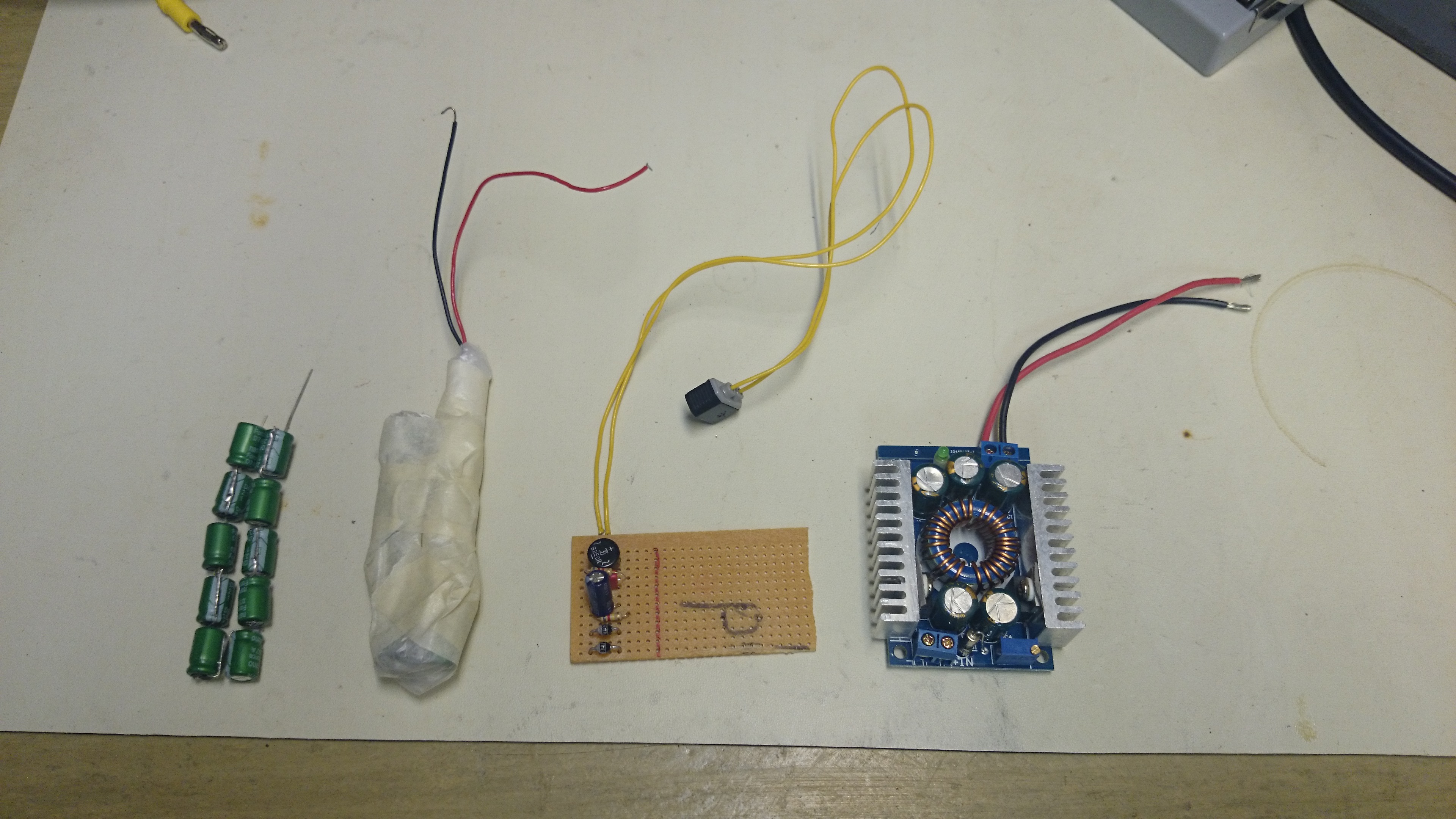 From left to right: capacitor strings (one wrapped in plastic and tape), rectifier/Zener board and DC/DC converter[/caption]
[caption id="attachment_935" align="alignnone" width="300"] Testing the crank dynamo with the rectifier board and capacitor strings, hooked up to an oscilloscope[/caption]
[caption id="attachment_934" align="alignnone" width="300"] Rectifier board, DC/DC regulator and capacitor strings, the latter two wrapped[/caption]
[caption id="attachment_933" align="alignnone" width="300"] Test fit. No worries[/caption]
Result
The device works surprisingly well. Cranking for 3-5 seconds makes MP3s of railway sounds play for around twenty seconds. Cranking ten seconds gives a playback time of around a minute. The maximum seems to be around two minutes.
We expect weather, particularly moisture, will be the thing that is most problematic. This hasn't turned out to be a problem so far with the battery solution, so we expect the new capacitor solution will work even better. The only thing left to do is build an identical power system and the second installation should be good to go.
Lessons learned
Supercapacitors have enough capacitance that you may need to consider their charge time, similar to batteries. There was also a potential problem from the Zeners putting out up to 24 V and the Arduino's linear regulator only handling up to 20 V. This means that for this solution the DC/DC converter was mandatory, since it takes up to 28 V. This could have been a problem is space inside the box was a larger issue. Luckily there's the upside of improved efficiency.
Improvements
There's a couple of improvements that could be done. The most obvious is to try to reduce the current draw from the Arduino by suspending the CPU while the Music Shield is working. Another one is to make the code "wall wart friendly" since at the moment it will play samples indefinitely until running out of power.
Source code
The code is not very complicated, but I had to apply some minor fixes to the Music_Player library in order to get it to link. I did not investigate why this problem occurred since a simple hack (moving ctrlState into the MusicPlayer class) fixed the problem.
Download: ljudstolpe-src.tar